Core8Bit bill of materials
The parts for one console. Equivalents are fine if they meet the requirements in each section.
Summary
| # | Part | Qty | Link |
|---|---|---|---|
| 1 | STM32H7 core board (STM32H7 + Winbond SDRAM + microSD + LCD FPC) | 1 | https://www.aliexpress.com/item/1005007953655418.html |
| 2 | Display HL043PQIPS-500, 4.3" IPS 500 nit, 480 x 272 | 1 | https://www.aliexpress.com/item/1005007673351797.html |
| 3 | DC-DC 21 V booster for the display backlight | 1 | https://www.aliexpress.com/item/1005006361814667.html |
| 4 | Step-up DC-DC module (boost #1 = switched 5 V, boost #2 = permanent core-board supply) | 2 | https://www.aliexpress.com/item/1005008606768282.html |
| 5 | Battery charger / "battery driver" board | 1 | https://www.aliexpress.com/item/1005009609557882.html |
| 6 | Li-Po 606090, 3800 mAh (4000 mAh is better) | 1 | https://www.aliexpress.com/item/1005005256977556.html |
| 7 | ESP32 DevKit (ESP32-WROOM-32, CH340, USB-C) | 1 | https://www.aliexpress.com/item/1005007900661803.html |
| 8 | Audio amplifier PAM8406 HW-301 (equivalents with volume trimmers are fine) | 1 | https://www.aliexpress.com/item/1005009698369580.html |
| 9a | Speakers 20 mm, for the speaker enclosures | 2 | https://www.aliexpress.com/item/1005008979038948.html |
| 9b | Cheap speakers, for builds without the enclosures | 2 | https://www.aliexpress.com/item/1005005024067956.html |
| 10 | Analog sticks | 2 | https://www.aliexpress.com/item/4000965985489.html |
| 11 | Push buttons (all the same) | 10 | https://www.aliexpress.com/item/1005005384244944.html |
| 12 | microSD 64 GB | 1 | https://www.aliexpress.com/item/1005009811584611.html |
| 13 | FFC 40-pin, 6 cm | 2 | https://www.aliexpress.com/item/1005006349829517.html |
| 14 | 40-pin FFC adapter boards | 2 | https://www.aliexpress.com/item/4000894435797.html |
| 15 | Display cover glass | 1 | https://www.aliexpress.com/item/1005005698549773.html |
| 16 | Soft rubber button caps | 10 | https://www.aliexpress.com/item/1005008179262125.html |
| 17 | Case screws 18 mm (M3) | 4 | https://www.aliexpress.com/item/32981974171.html |
| 18 | Case standoffs 14 mm | 4 | https://www.aliexpress.com/item/1005002279046513.html |
| 19 | Case: 3D-printed body + speaker enclosures, laser-cut faceplate | 1 | STL files will be sold on itch.io; case-only files as an optional donation |
| 20 | Mainboard: replaces the base plate and the wires (in development) | 1 | see mainboard.md and For the mainboard |
Also needed for the wired build:
- 8 × 33 Ω resistors: display CLK, HSYNC, VSYNC, DE (see assembly.md) and ESP32 SCK, MOSI, MISO, CS (see assembly.md);
- 2 × ferrite beads (≥ 1 A, for example 600 Ω @ 100 MHz) on the 5 V outputs of boost #1 and #2;
- 1 × ~10 kΩ pull-up for ESP32 GPIO5;
- 1 × ~100 kΩ pull-down for boost #1 EN;
- 2 × 220 µF electrolytics, 2 × 100 nF ceramics and a 10–47 µH (≥ 1 A) inductor for the amplifier supply filter;
- aluminium or copper foil tape to shield the FFC;
- hookup wire 28–30 AWG (signals) and 22–24 AWG (power).
The VS1003B MP3 module is not part of the wired build. The mainboard has a place for it, see For the mainboard.
For the mainboard
In development (mainboard.md). Only needed for the mainboard. Links, final values and quantities will follow with the KiCad project. Part numbers marked "for example" are examples.
| Part | Qty | Purpose |
|---|---|---|
| Two-layer mainboard PCB (base plate outline) | 1 | replaces base-plate.stl and the wires |
| USB-C connector (USB 2.0, 16 pins), board-mount | 1 | the single external port: charging, PC, OTG |
| TUSB320 (TI), USB Type-C CC controller, DRP mode | 1 | CC1/CC2, INT/ID output to a GPIO |
| Schottky diode SS34 or a P-MOSFET as an ideal diode | 1 | VBUS → charger board input |
| P-MOSFET VBUS load switch for OTG, for example the AO3401 series | 1 | 5 V of boost #1 → VBUS, driven by a GPIO |
| 22 Ω resistors | 2 | in series with D+ and D− |
| VBUS → PA9 divider resistors | 2 | starting value 10 kΩ / 20 kΩ |
| 33 Ω resistors | 8 | display CLK, HSYNC, VSYNC, DE; ESP32 SPI SCK, MOSI, CS (at the STM32) and MISO (at the ESP32) |
| Ferrite beads ≥ 1 A, 0805/1206 | 2 | 5 V outputs of boost #1 and #2 |
| SMD tactile micro button | 1 | hard reset (core board NRST → GND), pressed with a paperclip |
| 100 nF capacitor | 1 | on NRST next to the reset button, to GND (debounce) |
| VS1003B module (MP3 decoder) | 1 | SPI2: SCK PI1, MISO PC2, MOSI PC3, XRST PI2, XCS PI3, XDCS PI4, DREQ PI8 |
| ~1 µF capacitors + ~10 kΩ resistors | 4 each | passive mixing of the DAC and the VS1003B |
| DAC output RC filter (about 1 kΩ + 10 nF) | 2 each | |
| Inductor 10–47 µH (≥ 1 A), electrolytic ~220 µF, ceramic 100 nF | 1 / 1–2 / 2 | LC filter on the amplifier supply |
| 2.54 mm pin sockets and pin headers | per module | mount the modules on the back; height ≤ 9.4 mm under the back cover |
1. STM32H7 core board
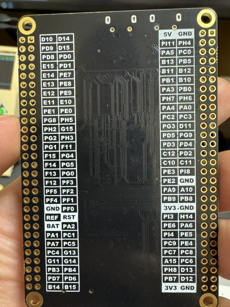
Link: https://www.aliexpress.com/item/1005007953655418.html
| On the board | "STM32H7 CORE" silkscreen; ST MCU, Winbond SDRAM, two micro-USB jacks ("USB" and "UART"), "SWD" connector, RESET and BOOT0 buttons, microSD slot, 40-pin "LCD interface" FPC. Two 2 x 29 headers with 5V, 3V3, GND, BAT, REF, RST. Full map: pinout.md → Core-board headers |
| Requirements | STM32H743IIT6 or STM32H753IIT6 in LQFP176; 25 MHz HSE and 32.768 kHz LSE crystals; 32 MB W9825G6KH-class SDRAM; W25Q128 QSPI flash; microSD on SDMMC2 |
2. Display HL043PQIPS-500 (4.3" IPS, 500 nit)
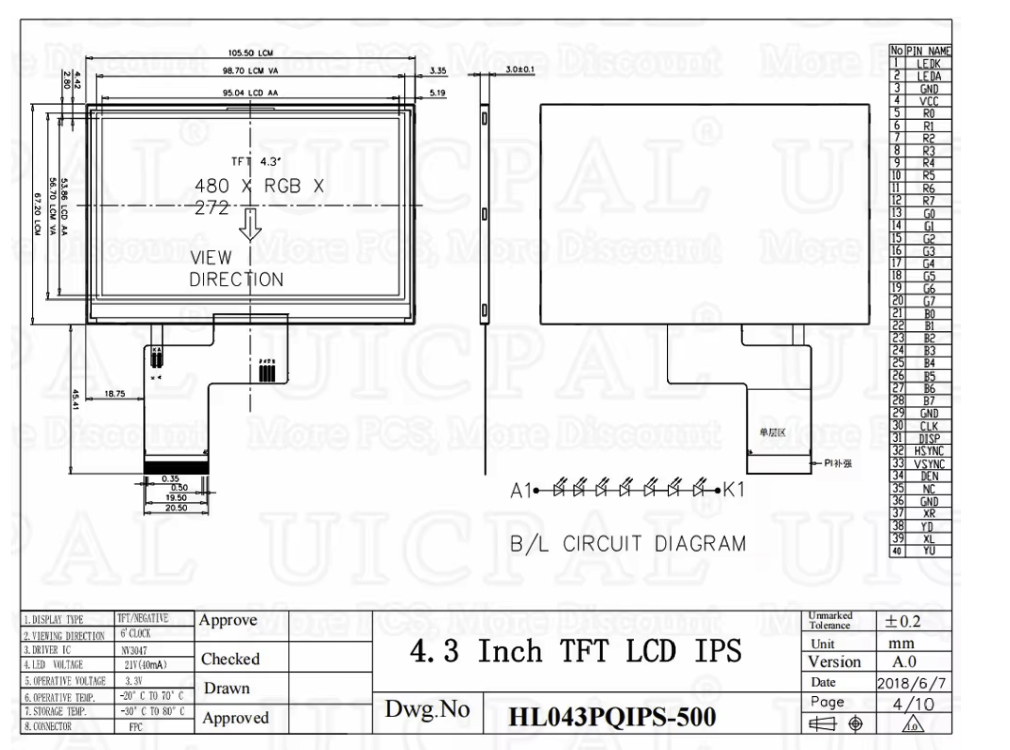
Link: https://www.aliexpress.com/item/1005007673351797.html
| Specification | 4.3" TFT IPS, 480 x RGB x 272, driver IC NV3047, logic 3.3 V, backlight 21 V / 40 mA (8 LEDs in series), 40-pin FPC with 0.5 mm pitch, active area 95.04 x 53.86 mm, outline 105.5 x 67.2 mm, operating −20…70 °C |
| Requirements | parallel RGB with DE, 480 x 272, 12.5 MHz pixel clock; DISP driven by PD5 (active HIGH) |
| Backlight | from the 21 V booster (#3) on the boost #1 rail; on/off with PE4, no dimming |
| Wiring | pinout.md → Panel FPC pinout |
3. DC-DC 21 V backlight booster
Link: https://www.aliexpress.com/item/1005006361814667.html
- Input: boost #1 (switched 5 V).
- Output: panel LEDA (pin 2) / LEDK (pin 1). Set it for 21 V / 40 mA maximum, see assembly.md.
4. Step-up DC-DC modules (x2)
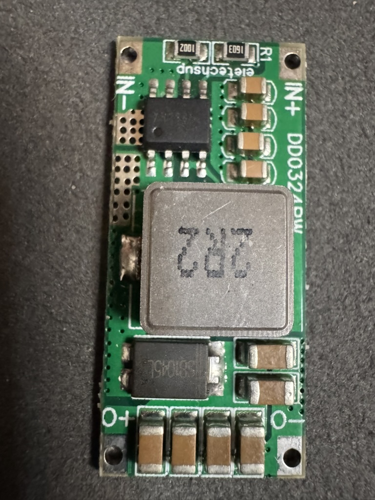
Link: https://www.aliexpress.com/item/1005008606768282.html
eletechsup module, silkscreen DD0324…W: SO-8 controller, shielded inductor, Schottky diode SB1045L, pads IN+, IN−, O+, O−. Output 5.0–5.1 V.
| Module | Role | Enable |
|---|---|---|
| Boost #1 | switched 5 V rail: ESP32 VIN, PAM8406 VCC, 21 V backlight booster | EN ← STM32 PE4 (HIGH = on), 100 kΩ pull-down to GND. The module has no EN pad: use the EN/SHDN pin of the SO-8 controller |
| Boost #2 | permanent supply of the STM32 core board | always on. Not used for reset: the hard reset shorts the core board's NRST to GND (see power.md) |
5. Battery charger / "battery driver" board
Link: https://www.aliexpress.com/item/1005009609557882.html
Sits between the cell and both boosts. The firmware measures the battery voltage only and detects charging from the voltage rise.
6. Li-Po battery 606090
Link: https://www.aliexpress.com/item/1005005256977556.html
- Size 606090, 3800 mAh; 4000 mAh is better.
- 1S cell with a protection board (BMS).
7. ESP32 DevKit
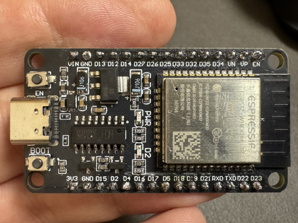
Link: https://www.aliexpress.com/item/1005007900661803.html
| On the board | ESP32-WROOM-32 module, CH340 USB-UART, USB-C jack, EN and BOOT buttons. Pins: VIN GND D13 D12 D14 D27 D26 D25 D33 D32 D35 D34 VN VP EN / 3V3 GND D15 D2 D4 D16 D17 D5 D18 D19 D21 RXD TXD D22 D23 |
| Requirements | classic ESP32 (not S2/S3/C3); ≥ 2 MB flash; D18/D23/D19/D5/D4 free for the SPI link |
| Power | VIN from boost #1 (switched 5 V) |
| Add | ~10 kΩ pull-up on D5 (GPIO5 is a strapping pin) |
8. Audio amplifier PAM8406 (HW-301)
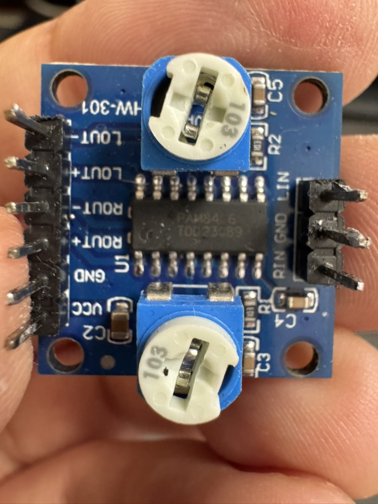
Link: https://www.aliexpress.com/item/1005009698369580.html
- PAM8406 with two 10 kΩ (
103) volume trimmers. Pins:LOUT- LOUT+ ROUT- ROUT+ GND VCCandLIN GND RIN. - Equivalents are fine; choose one with volume trimmers.
- Input from DAC1 (PA4/PA5); VCC from boost #1.
- Bridge-tied outputs: never connect
LOUT-/ROUT-to GND.
9. Speakers
- 20 mm, for the speaker enclosures of the case: https://www.aliexpress.com/item/1005008979038948.html
- Cheap speakers, for builds without the enclosures: https://www.aliexpress.com/item/1005005024067956.html
10. Analog sticks (x2)
Link: https://www.aliexpress.com/item/4000965985489.html
- 2-axis potentiometer sticks on 3.3 V.
- Right X → PA2, right Y → PA7, left X → PC1, left Y → PC4.
- Stick clicks are not used.
- Calibrate every new build in SELECT → Settings → Sticks.
11. Push buttons (x10, all the same)
Link: https://www.aliexpress.com/item/1005005384244944.html
Each button goes between its GPIO and 3.3 V; no external resistors. Caps: #16.
12. microSD card 64 GB
Link: https://www.aliexpress.com/item/1005009811584611.html
FAT32 or exFAT, one partition, high-speed capable. Card contents: assembly.md.
13–14. FFC 40-pin 6 cm (x2) and 40-pin FFC adapters (x2)
- FFC: https://www.aliexpress.com/item/1005006349829517.html
- Adapters: https://www.aliexpress.com/item/4000894435797.html
One adapter sits at the display, the other at the core-board "LCD interface" connector. The ribbon is folded under each adapter, and each fold mirrors the pin order (n ↔ 41 − n); see pinout.md. Shield the ribbon and both adapters with grounded foil (assembly.md).
15–18. Case hardware
| Part | Link |
|---|---|
| Display cover glass | https://www.aliexpress.com/item/1005005698549773.html |
| Soft rubber button caps | https://www.aliexpress.com/item/1005008179262125.html |
| Screws 18 mm | https://www.aliexpress.com/item/32981974171.html |
| Standoffs 14 mm | https://www.aliexpress.com/item/1005002279046513.html |
19. Case
- Body: 3D printed, with speaker enclosures. Faceplate: laser cut.
- The STL files for case + speaker enclosures will be sold on itch.io; case-only files as an optional donation.
Tools
| Tool | Use |
|---|---|
| ST-Link (V2/V3) | SWD flashing and debugging through the core board's "SWD" connector |
STM32CubeProgrammer (STM32_Programmer_CLI) |
flashing the BIOS |
ESP-IDF (idf.py) |
flashing the ESP32 over the DevKit USB-C |
| USB cables | micro-USB (core board), USB-C (ESP32) |